Lập trình C cho hệ thống nhúng (P8- Standby Function- Idle mode trong V850E)
1. Khái niệm Ở trong phần trước mình đã giới thiệu về HALT mode trong chức năng Standby funtion của V850E . Trong bài viết này mình sẽ tiếp tục giới thiệu về IDLE Mode của chức năng này. Trong khi HALT mode là mode mà trong đó chúng ta chỉ dừng clock hoạt động của CPU thì IDLE Mode sẽ dừng tất ...
1. Khái niệm
Ở trong phần trước mình đã giới thiệu về HALT mode trong chức năng Standby funtion của V850E . Trong bài viết này mình sẽ tiếp tục giới thiệu về IDLE Mode của chức năng này. Trong khi HALT mode là mode mà trong đó chúng ta chỉ dừng clock hoạt động của CPU thì IDLE Mode sẽ dừng tất cả mọi hoạt động của các mạch nội ngoại trừ những chức năng sau bô dao động, PLL, CSIB in the slave mode, clock monitor, low-voltage detector (LVI), power-on-clear circuit (POC).
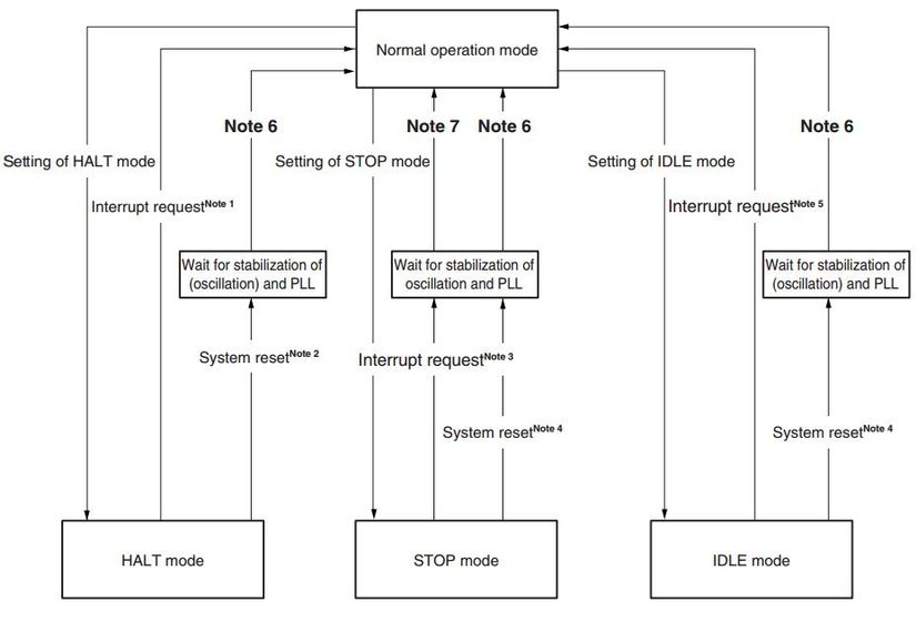
2. Hoạt động
IDLE mode được xác lập bằng cách clear (0) bit PSMR.PSM0 và set (1) cho bit PSC.STB trong mode hoạt động bình thường.Trong IDLE mode , bộ tạo xung clock và PLL sẽ tiếp tục hoạt động nhưng xung clock cung cấp cho CPU và các chức năng on-chip peripheral khác sẽ bị dừng lại.
3. Lập trình cho Idle mode hoạt động
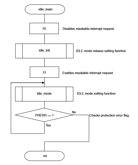
Sơ đồ khối MAIN Function
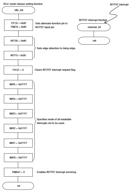
Sơ đồ khối IDLE mode Release setting function
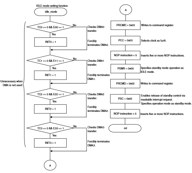
Sơ đồ khối IDLE mode Setting function
Sourecode
/*************************************************************************/
/*	idle.c			        Standby function					         */
/*                                                                       */
/*      IDLE mode is set and it is released by an external interrupt 	 */
/*	    request signal.  The mode is released by using an unmasked 		 */
/*		external interrupt signal (INTP7).				 				 */
/*																		 */
/*  - Procedure for releasing IDLE mode									 */
/*		IDLE mode can be released under the following three conditions.	 */
/*		 1. Unmasked external interrupt signal							 */
/*		 2. Unmasked internal interrupt signal from peripheral functions */
/*          operable in IDLE mode	                                     */
/*		 3. RESET pin input												 */
/*		Normal operation mode is entered after IDLE mode has been 		 */
/*		released.														 */
/*																		 */
/*	- Operation after releasing IDLE mode by interrupt request signal	 */
/*		- Interrupt enabled (EI) status	...Execution branches to the 	 */
/*         handler address or the next instruction is executed 			 */
/* 		- Interrupt disabled (DI) status			 					 */
/*			...The next instruction is executed.						 */
/*																		 */
/*************************************************************************/
/*───────────────────────────────────
*   Pragma Instructions
* ───────────────────────────────────
*/
#pragma ioreg							/* Peripheral I/O register name enable specification */
#pragma interrupt INTP07	external_int	/* INTP07 interrupt function declaration */
/*───────────────────────────────────
*	Function Prototypes
*───────────────────────────────────
*/
void idle_main(void);					/* IDLE mode function */
void idle_init(void);					/* IDLE mode release setting function */
void idle_mode(void);					/* IDLE mode setting function */
/*───────────────────────────────────
*   Idle_Main Function
* ───────────────────────────────────
*/
void idle_main(void)
{
	__DI();								/* Maskable interrupt disable */

	idle_init();						/* IDLE mode release setting function */

	__EI();								/* Maskable interrupt enable */

	do{
		idle_mode();					/* IDLE mode function */

	}while(PRERR);						/* Written in a correct sequence? */

	return;

}

/*───────────────────────────────────
*   Idle_Init Function
* ───────────────────────────────────
*/
void idle_init(void)
{
	PFC0 = 0x00;						/* Set INTP7 input. */
	PMC0 = 0x80;						/* Set the P00 pin to the INTP7 input pin. */
										/* Setting of P0 and PM0 not required */

	/* Detect an edge, because an external interrupt will be used. */
	INTR0 = 0x80;						/* Rising edge */
	INTF0 = 0x00;						/* Rising edge */

	PIF07 = 0;							/* INTP7 interrupt request flag clear */

	IMR5 = 0xFFFF;						/* Unused interrupt mask */
	IMR4 = 0xFFFF;						/* Unused interrupt mask */
	IMR3 = 0xFFFF;						/* Unused interrupt mask */
	IMR2 = 0xFFFF;						/* Unused interrupt mask */
	IMR1 = 0xFFFF;						/* Unused interrupt mask */
	IMR0 = 0xFFFF;						/* Unused interrupt mask */

	PMK07 = 0;							/* Enable INTP7 interrupt servicing */

	return;

}

/*───────────────────────────────────
*   Idle_Mode Function
* ───────────────────────────────────
*/
void idle_mode(void)
{
	/* Since DMA transfer needs to be terminated before data setting to a special register,
	DMA is forcibly terminated in this sample. */

	if(TC0 == 0 && E00 == 1){			/* DMA0 transfer judgment */
		INIT0 = 1;						/* DMA0 forcible termination */
	}
	if(TC1 == 0 && E11 == 1){			/* DMA1 transfer judgment */
		INIT1 = 1;						/* DMA1 forcible termination */
	}
	if(TC2 == 0 && E22 == 1){			/* DMA2 transfer judgment */
		INIT2 = 1;						/* DMA2 forcible termination */
	}
	if(TC3 == 0 && E33 == 1){			/* DMA3 transfer judgment */
		INIT3 = 1;						/* DMA3 forcible termination了 */
	}

	/* The PCC register, which is a special register, can be written only via a combination of specific sequences. */
	/* bit 1, bit 0: Clock selection */
	/* Clock selection: fxx/8 */
	__asm("mov 0x03, r10");				/* Set in a general-purpose register data to be set in a special register. */
	__asm("st.b r10, PRCMD[r0]");		/* Write to the PRCMD register. */
	__asm("st.b r10, PCC[r0]");			/* PCC register setting */
	__asm("nop");						/* Insert at least five NOP instructions. */
	__asm("nop");
	__asm("nop");
	__asm("nop");
	__asm("nop");

	/* Specification of operation in software standby mode */
	/* Set to IDLE mode. */
	PSMR  = 0x00;						/* bit 0: Bit for specifying IDLE/STOP mode */
										/* 1: STOP mode, 0: IDLE mode */
										/* Specify IDLE mode. */

	/* Register for controlling standby function */
	/* bit 4: Control of standby mode by maskable interrupt request */
	/* 1: Standby mode release disabled, 0: Standby mode release enabled */
	/* bit 1: Specification of operating mode */
	/* 1: Standby mode, 0: Normal mode */
	__asm("mov 0x02, r10");				/* Set in a general-purpose register data to be set in a special register. */
	__asm("st.b r10, PRCMD[r0]");		/* Write to the PRCMD register. */
	__asm("st.b r10, PSC[r0]");			/* Standby mode setting */
	__asm("nop");						/* Insert at least five NOP instructions. */
	__asm("nop");
	__asm("nop");
	__asm("nop");
	__asm("nop");

	return;
}

/*───────────────────────────────────
*   Interrupt Function
* ───────────────────────────────────
*/
__interrupt
void external_int(void)
{

}